Temperature controller modules from China can be found on Amazon or Ebay for only about $15. For a little more you can build your own temperature controller.
Available Controller Types
Controllers with relays that turn on or off can be grouped in PID controllers, and threshold or on/off controllers.
PID (Proportional, Integral, Derivative) based control gives you the capability to learn to control virtually any system optimally, to minimize overshoot and delay, switching on and off at the right time. It is perfect for keeping the temperature constant with minimal fluctuation.
Threshold controllers in contrast are relatively dumb and switch on or off depending on set temperature thresholds. The remainder of this article will focus on threshold controllers.
Threshold Controller Features
Threshold controllers come in a number of flavors and have more functions than you would expect. We can set a threshold temperature, and specify if exceeding it should close a switch, or if dropping below that threshold should close the switch. One would use the former with a cooling system and the latter with a heater. In addition, we can set a hysteresis offset, i.e. shifting the threshold after it is exceeded or dropped below lower or higher, respectively, to avoid fast and jittery switching on and off when exactly at the threshold. Finally, we can set a turn-on delay that is designed to protect cooling systems.
Different models of controllers will be available for switching lower voltage, or high-voltage circuits using an internal electromechanical relay, solid-state relay, or just a voltage output, and operate in degrees Celcius, or Farenheit, and use different types of sensors of which the RTD is the more common type.
Building a Controller Box
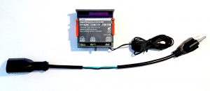
Probably the cheapest way to build a controller is buying the module, a 1 foot extension cord, and connecting these together with some cutting skill. It is not the safest and most robust, and thus not recommended. (Refer to our upcoming article describing a better way.)
[ ] Buy the controller and a 1-foot extension cord.
[ ] Cut part of the jacket of the extension cord away using a sharp knife, without damaging the insulation of the wires.
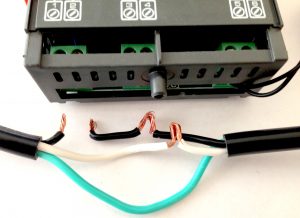
[ ] Remove part of the insulation of the black and white wires using a sharp knife, aligning the bare wire to the power terminal blocks #3 and #4 (in this case) where the power plug is to the right
[ ] Cut the black (live) wire and strip it at terminal block #1 (in this case) and strip both ends aligning to relay terminals #1 and #2 (in this case).
[ ] Connect and screw the protective shielding cover back on the module.
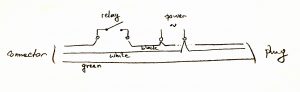
This arrangement creates a controller where the power supply is the same as the switched supply to the load or appliance to be controlled. Check the allowed voltage and wattage of the load, and of course make sure you are using the right controller for your power outlet voltage.
The same approach can be used to wire a separate power supply cord, and a cord for a switched load. The plastic cover on the back of the controller helps making this more sturdy, but for proper cord strain relief the controller should be placed in a box and cord must have strain relief installed.
Controller Programming Reference
Next to understanding how exactly these temperature controllers actually behave, the next worst part is remembering how to operate them. The manuals are typically of very low quality, and the number of buttons is kept minimal to keep cost low, but you need to remember a couple of combinations. The information below is on a couple of typical temperature controllers, in real English!
For BYT-3A016 (BAYITE) – ONE RELAY HEAT OR COOL
Manual operation
| Key | Function | Mode |
| [RST] hold 3s. | turn controller off / turn controller on | regular operation |
| [SET] | show or set temperature threshold T0, or store any changes and show current temperature T | regular operation |
| [up] | increase the threshold parameter value T0 | set temperature |
| [down] | decrease the threshold parameter value T0 | set temperature |
| [SET] hold 3s. | enter controller (other) parameter setting/editing mode | regular operation |
| [up]/[down] | cycle through settable parameters | select HC – d – AH – AL – HS – LS – CA – PT |
| [SET] | show the currently selected parameter value, or return to parameter selection | select HC – d – AH – AL – HS – LS – CA – PT, or set selected parameter |
| [up]/[down] | set the parameter value of parameter selected | set selected parameter |
| [RST] | store parameters and return to regular operation | select HC – d – AH – AL – HS – LS – CA – PT |
Parameters
| Parameter | Meaning | Details |
| SET | Temperature target T0 | Degrees (e.g. -58.0…230 deg.F) |
| HC | Operating mode | H (heating) or C (cooling) |
| d | Temperature difference TD | Degrees (e.g. 0.1…25 deg.F) |
| HS | Max target temperature T0 set limit HS | Degrees (e.g. LS…230 deg.F) |
| LS | Min target temperature T0 set limit LS | Degrees (e.g. -58…HS deg.F) |
| PT | Delay time value td | Minutes (e.g. 0…30 min.); 0=off |
| AH | High temp. difference alert threshold | Degrees (e.g. 0…25 deg.F); 0=no alert/off |
| AL | Low temp. difference alert threshold | Degrees (e.g. 0…25 deg.F); 0=no alert/off |
| CA | Temperature addition offset calibration | Degrees (e.g. -9…9 deg. F) |
Controller operation
Depending on the mode of operation of the relay being heating or cooling:
Heating mode: If measured temperature T <= T0-TD, the relay will engage, until T crosses above T0 level.
Cooling mode: If measured temperature T >= T0+TD, the relay will engage, until T crosses below T0 level, but the relay engages only after td minutes have passed since the last time the cooling relay dis-engaged.
To keep temperature within approx. T1 and T2, set the threshold equal to T0:=T2 and TD:=(T2-T1) in heating mode, or T0:=T1 and TD:=(T2-T1) in cooling mode.
For STC-1000 – TWO RELAYS HEAT/COOL
Manual operation
| Key | Function | Mode |
| [up] hold | show currently set temperature threshold value | regular operation |
| [down] hold | show the temperature difference | regular operation |
| [O] hold 3s. | turn controller off / turn controller on | regular operation |
| [S] hold 3s. | enter controller parameter setting/editing mode | regular operation |
| [up]/[down] | cycle through four settable parameters | set F1 – F2 – F3 – F4 |
| [S] | show the currently set parameter value | set F1 – F2 – F3 – F4 |
| [S] + [up]/[down] | set the parameter value of parameter selected | set F1 – F2 – F3 – F4 |
| [O] | store parameters and return to regular operation | set F1 – F2 – F3 – F4 |
Parameters
| Parameter | Meaning | Details |
| F1 | Temperature threshold T0 | Degrees (e.g. -50.0…99.9 deg.C) |
| F2 | Temperature difference TD | Degrees (e.g. 0.3…10.0 deg.C) |
| F3 | Delay time value td | Minutes (e.g.1…10 min.) |
| F4 | Temperature addition offset calibration | Adjust displayed temperature match true temperature. Degrees (e.g.-10…10 deg.C) |
Controller operation
Only one of “cooling” relay and “heating” relay will be engaged, or neither.
If measured temperature T <= T0-TD, the “heating” relay will engage, until T crosses above T0 level.
If measured temperature T >= T0+TD, the “cooling” relay will engage, until T crosses below T0 level, but the relay engages only after td minutes have passed since the last time the cooling relay dis-engaged.
To keep temperature within approx. T1 and T2, set the threshold equal to T0:=(T1+T2)/2 and TD:=(T2-T1).
References
Wiring color coding (web)
Introduction to Temperature Controls (web)
Farenheit to Celcius converions (web)
Disclaimer: We are not responsible for any damages as the result of reading our article. We stress that you must confirm the accuracy of information in this article yourself, and confirm safety thoroughly and professionally before placing any hardware to practical use.
updated: 20170213
This writeup was very useful. If you add the polarity for 12vDC connections that would be helpful. Thank you.
Thanks, this helped me figure out the menus! I’ve had this module running for about 4 years and it is still working good!